A New Mod For GZDooM and
DooM Legacy
Main | Work In Progress | Notes | Goals and Plans | Screen Shots | Download | DeiMWolf Forum
A New Mod For GZDooM and
DooM Legacy
Main | Work In Progress | Notes | Goals and Plans | Screen Shots | Download | DeiMWolf Forum
Skip to:
Introduction
Current progress
January 20, 2008
December 30, 2007
October 6, 2007
May 15, 2007
May 8, 2007
May 1, 2007
February 23, 2007
February 7, 2007
December 24, 2006
July 22, 2006
July 14, 2006
June 22, 2006As part of my goal to make all new graphics for DeiMWolf, I wanted to depict the player holding various weapons he would likely find inside a German installation during his escape. To this end, I purchased real German bayonets, and an air soft replica of a German submachine gun, the MP40.
For the heaviest weapon available in the game I also purchased vacuuformed replica of an MG34 machine gun from Cushman Paintball ...
It was possibly one of the worst decisions I have ever made. Rarely have I ever been so disappointed. I've done vacuuforming myself, and I can honestly say that this was one of the worst vacuuforming jobs I have ever seen. Take a look at these scans to see just how bad this horrible model is:

It almost looks as if somebody dropped it into a vat of black pancake batter.

What kind of sick people would sell crap like this?
(Cushman Paintball. That's who.)
It was obvious from the moment I opened the box that the Cushman could never be used, even at coarse resolution used by DooM.
I had spent over $110.00 CDN buying this blasted thing ($50.00 US for the main part, plus $10 US for an equally bad bipod, plus $20.00 US for shipping, times exchange, plus an additional 7% GST tacked on to it when it crossed the border), and all I got for my trouble was a complete and utter piece of garbage I couldn't use.
And so I sat and pondered what to do next.
After three months of pondering, I remembered that the trashy piece of vacuuformed garbage was in fact vacuuformed around an original that included many real MG34 parts. The replica may not be any good as a replica itself, but did have just enough detail that I could probably take some fairly decent measurements form it, and from these measurements, along with careful study of actual MG34 photos, it may actually be possible to build a full scale MG34 model from scratch!
So began work on this projecta project on which another project depends.
The goal of this project is to create an accurately detailed full sized model of an MG34 machine gun. If successful, it should accurate enough to fool even an expert at just a few paces. I will have my prop for use in DeiMWolf, and as a bonus, I will have fantastic conversation piece to hang on my wall!
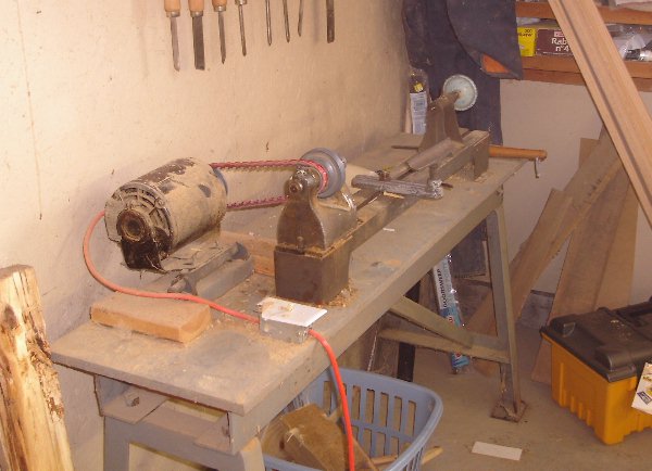
For the purpose of working on the receiver, I began work on building a simple wooden lathe powered by a drill. However, as I was working on it, my brother informed me that he had a small professional lathe sitting in his back room workshop that hadnt been used in years.
Doh!
Anyway, It looked to me like a little field trip out to my brothers place was in order, and here was the little adventure we had.
It may not look like much, but this small lathe was once used in a professional workshop making turnings for fine furniture. Now, sad but true, it has been reduced to the indignity of working for me.
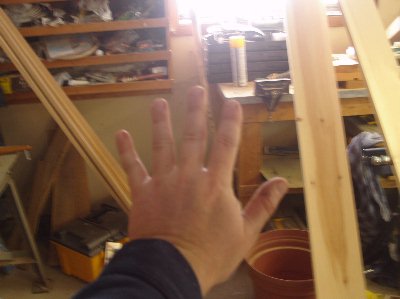
Before starting, I decided to do a quick hand and finger count, just in case.
Two hands ... four fingers on each ... two thumbs. Good. Good.
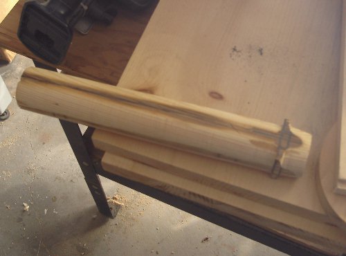
Before trying out the lathe on the real thing, my brother and I decided to run a few tests on old scraps to get used to using the lathe, and to get an idea of just what kind of mayhem we should expect. The results were not pretty. The soft wood had a tendency to tear away from the dead centre on the tail stock. It was not very promising. The pieces we were using for the test were 4 × 4s however, and after some thought we figured that the more massive size of these pieces was the root of our troubles, so we decided to go ahead and take a chance with the real piece.
My brother started off, and had no trouble at first.
He then handed the gouge of to me. As I began rounding off the corners however, the imbalance of the piece in the lathe proved too much. The end of the piece of wood tore off the dead centre of the tail stock, then the wood got thrown violently from the lathe, and klonked me across the side of the head. I was not injured, but I was not pleased either.
My brother trimmed off the torn out end of the wood to allow it to go back on to the dead centre. As he went off to do an errand, I decided to try something, which turned out to be a wise move. Rather than simply returning the piece to the lathe right away, I used a utility knife to whittle away some of the material from the corners of the wood.
This did indeed turn out to be a wise move. When the piece was returned to the lathe, much of the imbalance and its associated violent vibration was eliminated. The piece spun much more easily, and I had no further trouble.
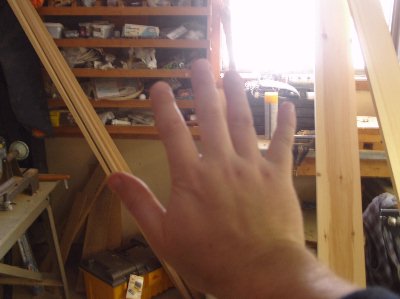
Time to do another hand and finger count.
Hmmm ...
Two hands ... a full compliment of fingers ... two thumbs.
Excellent!
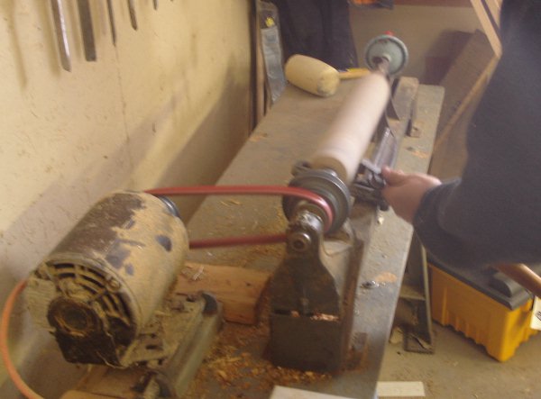
Now lets see how the the thing looks in conjunction with some of the authentic parts.
Okay. So it still doesn't look like an MG34 receiver yet. Who cares? It is just the wooden core, and it definitely looks a lot closer to the real thing than it did a few weeks ago.
Soon it will be covered in polyester resin, lathed again, then sanded and detailed. Oh yes. The top third of it will be cut off as well.
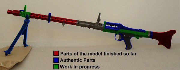
By the way, since it is obvious that it is going to take time to complete this part of the model, robbing me of the satisfaction of adding more red to the progress diagram, I have decided to add a new colour, green, to the diagram to show parts that are currently being worked on, but have not been completed yet.
I hope that doesn't confuse you too much. :-P
I have come to the inescapable conclusion that the engineer who designed the MG34 must have been either completely insane or joking. The amount of machining on the receiver is nothing short of ludicrous, and guess what I now have to try to reproduce! It is no wonder the Germans switched to producing the MG42. All this detailed millwork is nuts!
What my basic plan is for creating the receiver is to start with a wooden core spun on a lathe into a rough approximation of the receiver, excluding any details that stick out (Note: Anyone who believes the fact I dont have a lathe is going to stop me doesnt know me very well.). Once the core is created, I will coat it with polyester resin. This will hide the wood grain and allow me to create a cleaner surface that more closely resembles milled metal. Slots and recessed details can cut in, and then the rest of the details that do stick out can be constructed as separate pieces and mortised into the main piece.
That is my plan at least.
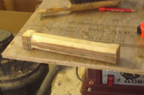
What you see before you is a very special piece of wood.
Why is it so special?
Ill tell you.
This piece of wood is a 2 × 8 a TRUE 2 × 8. It was sawn 87 years ago, back in the days before the lumber companies started screwing their customers, so it is not 1 1/2" × 7 1/2" like the 2 × 8s you find in lumber stores today. This one is actually 2" × 8", minus about 1/8" from the kerf of the saw and almost a century of drying. Up until I found this, I was worried about having to laminate multiple pieces of wood together to form the wooden core of my receiver, but since this piece of wood happened to be the same width as the receiver is supposed to be, I no longer needed to worry about laminating pieces of wood. All I needed to do was saw a 2 inch piece from one side of this old scrap, and I would be golden.
So I ran this wonderful piece of wood through the table saw and got the true 2 × 2 I needed. Then I popped it into my cheap and cruddy mitre box and sawed it to 13 inches long, just slightly longer than the finished receiver is supposed to be.
It doesn't quite look like an MG34 receiver yet, ...
... but it will soon enough. Trust me.
Okay. It has been almost five months since I last updated.
Big deal.
I havent been doing a whole lot of work on the MG34 over this time (Its a hobby! Okay?!?), but I do have a fair bit of information to bring you up to date. Lets see if this will make up for all the silence.
Way back at the beginning of this project I made a front sight out of poyester resin. Unfortunately, it got broken in July. After considering different ways of fixing it and reinforcing the broken section, I finally decided to toss the broken part, and immediately made a replacement from a block of aluminum. Using the flash cone catch as a guide, I was able to make this new one a little more accurate than the first one.
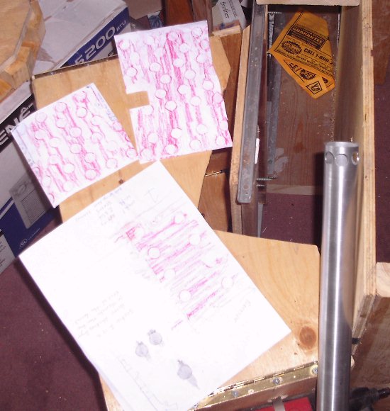
Back in May, I convinced Rob Slater, a Star Wars reenactor who owns a real demilitarized MG34, to wrap some paper around the barrel shroud of his MG34 and take some rubbings for me. This he did promptly, and I soon received these nuggets of valuable information the morning of May 23. Below is a photo of the rubbings, in glorious pink crayon, along with the aluminum tube I am using for the barrel shroud. All of these happen to be sitting atop the duplicator I used to make the butt.
I was glad to have the rubbings, because they confirmed something I had just observed visually on some MG34 photos I was looking at. Normally, one would expect the holes in a guns barrel shroud to alternate between 90° (N,S,E,W) positions and 45° positions (NE,SE,SW,NW), but although the 90° position holes were in the right places, the supposedly 45° holes were not mid way between the 90° holes, but closer to one side than the other, as in these photos below.


This meant that they were offset by something other than 45°. The rubbings confirmed this, showing the offset to be just 30°, not 45°.
The rubbing also showed me the correct size of the holes, 15 mm (9/16"), and indicated the diameter of the barrel shroud as being 39 or 40 mm (~1 1/2").
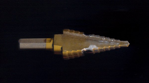
Now, I had a few problems to overcome before I could drill the holes for the shroud. The first one was simply finding a 9/16" cobalt or titanium bit the drill the tube with. Hardware stores, at least around here, generally don't sell cobalt or titanium drill bits in sizes larger than 1/4", and almost never sell bits larger than 1/2", except for spade bits, which are not usable on metal. I did finally get hold of a titanium step bit, which included 9/16" as one of its steps, but there was only 1/8" of vertical distance between steps. In test drillings, I found that by the time the 9/16" step drilled through the lower part of the tubes curve, the next larger step (5/8") would already be drilling into the upper part of the curve. This almost proved to be a show stopper, but then I spent an hour or two grinding away that larger step (ruining two grinding bits in the process), and the day was saved!
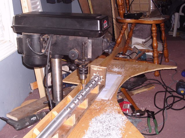
The next problem was figuring out how to make sure I drilled all the holes in exactly the right places. I could have used the rubbings as templates and drilled the holes with a hand drill, but that would not give me the precision I wanted. The holes would not be consistent, and the barrel shroud would look Home-made, not professional. What I needed was my drill press, and a jig, or, as it turned out, a pair of jigs that fit together.
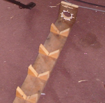
The first jig was to keep the aluminum tube steady and at the correct angle(s) while drilling. This is what I came up with.
The angled blocks attached to the board form a series of V notches to hold the tube in place. At the end of the board is another block of wood. This block has a series of notches in it at the proper angles, and a hole through which the tube fits. I drilled a small hole through the tube at one end, and epoxied a roofing nail into the hole, creating a small peg to fit into the notches. To keep the tube turned to the right angle, all I needed to do was insert the peg into the appropriate notch.
The second jig is simply a piece of quarter inch plywood with a 1" × 2" attached to create a fence (You can even see a nice big curve where I cut a Viking shield out of it back in August. Hee hee.). The plywood was clamped to the table of the drill press, and a series of small holes was drilled in the plywood at the correct distances. Nails were inserted into the holes to act as bench stops. This way, each set of holes was kept consistent with its fellows.
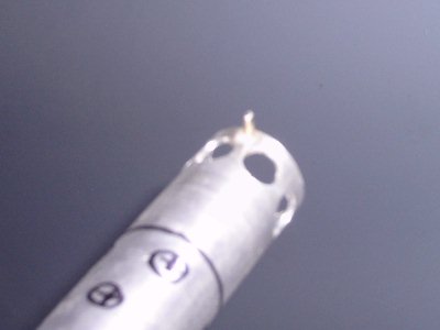
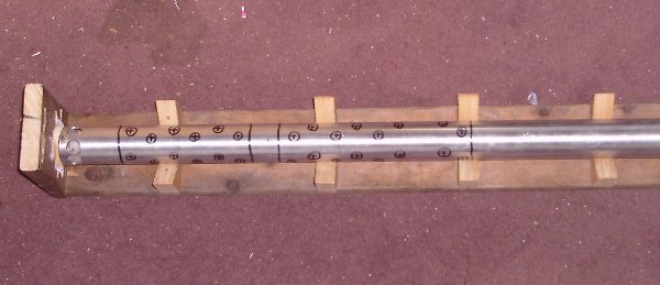
Now, not every position where a hole can be actually has a hole at that position. To make sure I didn't drill any holes where they ought not to be, I took a few minutes and roughly marked out where holes should be, leaving some blank where holes are not supposed to go, and in some cases writing NO to keep myself from accidentally drilling holes where there should be none.
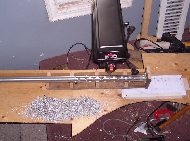
Finally, it was time to go to work ...
... and after roughly an hour and a half of slowly and carefully drilling holes, I was done.
It is nice to see a major portion of the model completed.
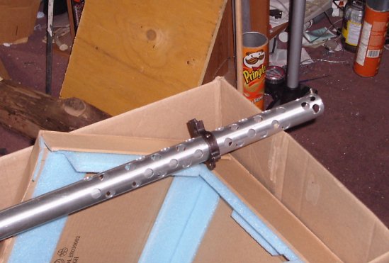
The black thing is the antiaircraft sight mount, which I have bent back into the proper shape. A pair of rings on either side of it, the bipod catch on the underside, and some features at the front, where that cluster of test holes is, will have to be added before this section of the barrel shroud is done, but the drilling of the tube is a major step forward in the project.
Whoa hoo! Red is finally catching up to blue on the progress diagram!
Main | Work In Progress | Notes | Goals and Plans | Screen Shots | Download